
End User— Proper Biological Indicator Placement During VH2O2 Decontamination Cycles
By Kurt McCauley
As is true with all sterilization processes, vaporized hydrogen peroxide (VH2O2,) has clearly defined performance limits, many of which are unique to this process. Vaporized hydrogen peroxide is primarily effective as a surface decontaminant and penetrates rather poorly when compared with other more traditional sterilization processes. Due to this limitation, proper biological indicator (BI) placement during the decontamination cycle is critical in order for the BI to function as designed.
The three general BI types used for monitoring VH2O2 cycles are a packaged disc, an unpackaged ribbon, and a self-contained biological indicator (SCBI). A detailed description of these BI types will be discussed as well as directions on their proper placement in the isolator. Additional information on their use is enclosed with each package of BI product.
The Packaged BI (HMV-091, KCD-404, NAS-152, and LOG-456)
The physical configuration of these BIs is a stainless-steel disc inoculated with Geobacillus stearothermophilus spores packaged into a permeable Tyvek® envelope.The spore placement is on the concave side of the disc, packaged with this side of the disc facing the printed side of the envelope.
When positioning the BIs in the isolator, the printed side should always face towards the vapor flow, and at no time should it be obstructed. Ideally, the BI should be positioned such that the flow of vapor can pass by both sides of the envelope. A hole has been provided in the envelope so the BI can be hung from a fixture on the wall, ceiling, or other structure. BI units can be hung individually or in multiples as demonstrated in Figure 1.
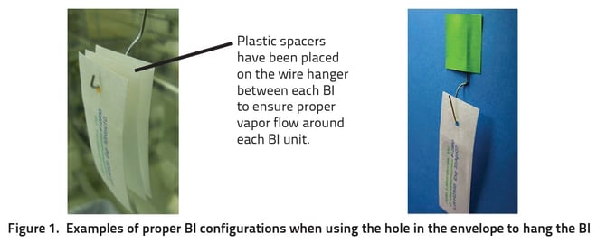
An adhesive tape can also be used to fix BIs into place. The best practice here is to place the tape on the peel flaps of the envelope and then secure it to the surface being monitored, as illustrated in Figure 2. Care must be taken not to cover the pocket of the envelope with the tape which would obstruct the vapor flow, as illustrated in Figure 3.
Note: Not all adhesive tapes are equal. Tape that absorbs or catalyzes hydrogen peroxide should not be used. Additionally, tape that leaves a residual behind once it is removed should be avoided.
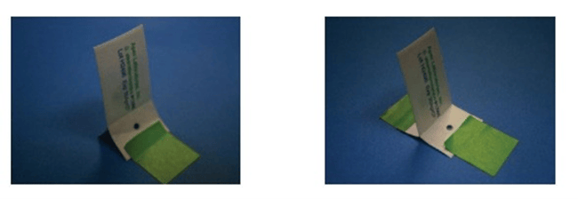

Figure 2. Examples of proper BI placement when using adhesive tape to position the BI

Figure 3. Examples of IMPROPER BI placement when using adhesive tape
Another common practice, especially when using large numbers of BIs, is to write identifying marks on each BI. These marks help identify the location in which the BI was placed as demonstrated in the first photograph in Figure 4. As is the case with the tape, placing marks on the pocket of the envelope should be avoided. Certain types of ink may also catalyze hydrogen peroxide and should be avoided completely.
Due to poor vapor flow, placing BIs into or underneath bottles (Figure 4) or other containers is not recommended.
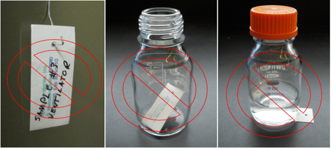
Figure 4. Examples of IMPROPER BI use: writing on the face of the package and placing BI into or underneath a container.
During large validations where hundreds of BIs are used in a single decontamination cycle, the BIs are often placed in the isolator the day prior to the exposure. Also prior to the exposure, thorough cleaning or wipe-down of the isolator may occur. When this happens, and especially if the isolator is sealed after the wipe-down, the internal humidity may be high.
It has been demonstrated that BIs stored under high humidity conditions may have an increased resistance to hydrogen peroxide. It is recommended that when both BI placement and isolator cleaning happen the day prior to exposure, the isolator is not sealed to prevent increased humidity levels.
The Unpackaged Ribbon BI (SBC-327)
The physical configuration of this BI is a stainless-steel ribbon inoculated on one end with G. stearothermophilus spores. The inoculated area of the BI is clearly visible (a 104 spore load is still visible but not as obvious as a 105 or 106 load). The BIs are placed in a protective ‘‘cartridge belt” until the time of use.
Note: Sterile cartridge belts are available for transport of ribbons to the lab following exposure to the decontaminating agent.
The ribbon BI can also be positioned by hanging or taping in place. The inoculated area should always be positioned so that it faces outward and ideally so that the vapor can flow by both sides of the ribbon as demonstrated in Figure 5.

Figure 5. Examples of proper (left photograph) and improper (right photograph) BI placement
An advantage of this BI is that the inoculated area of the ribbon can be placed into locations where the disc BI cannot physically fit, including restricted areas where the vapor penetration may be in question. Dead legs in an isolator are certainly areas of concern and should be eliminated or minimized. The ribbon can be useful in these cases in identifying the gas penetration down dead legs. The inoculated area can be placed into the area of concern, and if sufficient vapor flow occurs through this restriction, the spores on the BI will be inactivated. However, if the result after culturing the BI is ‘‘growth”, then it is fair to assume that inadequate vapor flow is occurring, and the area is a true dead leg (Figure 6).
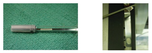 Figure 6. Examples of ribbon BIs in dead leg (left) and hanging on an isolator fixture (right)
The Self-Contained BI (AP-VH2O2-SC-S12980/6)
The physical configuration of this SCBI is quite similar to SCBIs used to monitor sterilization processes with one significant difference, the placement of the spore carrier. Other SCBIs contain the spore carrier on the bottom of the plastic vial, but to compensate for the poor penetration ability of VH2O2, the Apex® EZTest® BI presents the spores directly underneath the Tyvek filter (Figure 7.) The spores and stainless-steel carrier are identical to those used in the HMV-091 BI. The vents in the cap are designed to allow maximum vapor flow while the culture medium is designed for optimal spore recovery.
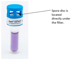 Figure 7. Apex EZTest Self-Contained BI
The SCBIs can be positioned in the isolator by hanging on a clip (through the large vent holes in the cap) or by standing on a solid surface as demonstrated in Figure 8.
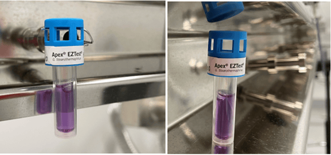
Figure 8. Examples of SCBI hanging by wire clip (left) and standing on an isolator fixture (right)
Post-exposure handling
Post-exposure BI handling is also important. In some cases, the BIs are cultured in the isolator, and in other cases, they are transported to a lab for culture. Tyvek is not known to absorb significant amounts of hydrogen peroxide; however, when transporting the BIs to the lab, they should be placed into a porous bag (e.g., Tyvek) to allow for any outgassing. The positive control BIs can be transported to the lab at the same time, but they must never be placed into the same bag as the exposed units.
When culturing the ribbon BIs, only the inoculated end of the carrier should be cultured.
This can be accomplished by cutting it free from the ribbon with sterile scissors as demonstrated in Figure 9. To culture the entire ribbon, especially if it has been held in place with tape, would invite false-positive results.
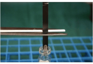
Figure 9. Example of culturing inoculated area of ribbon BI
The spores in the SCBI are cultured by compressing the sides of the plastic vial until the glass ampoule containing the growth media ruptures. This act not only releases the culture media, but also allows the spore disc to drop into the vial (Figure 10). The glass must be fractured into small pieces to allow the disc to drop completely into the media. To prevent media evaporation during incubation, the cap on the unit is depressed until the SCBI unit is completely sealed. Upon incubation, viable spores will turn the media yellow in color indicating a positive result, while a growth negative unit will remain purple (Figure 10).
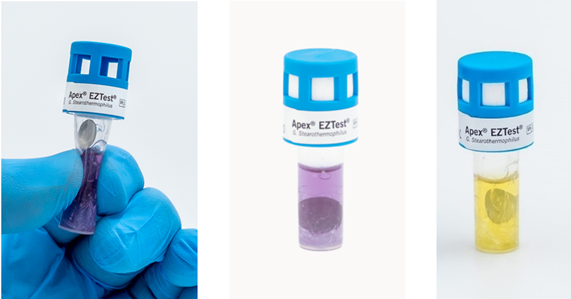
Figure 10. Apex EZTest SCBI being cultured (left), after being sealed (middle), and an example of a growth positive unit (right)
When a positive BI is obtained after a decontamination cycle, the results must be investigated. Was the result caused by a “hyper resistant” BI, poor BI positioning in the isolator, post exposure contamination, or perhaps the biological indicator is “indicating” there may truly be a problem in that particular location of the isolator? As was emphasized here, a few considerations in the pre-exposure setup and post-exposure handling should not be overlooked. As noted in a previous Spore News titled “Using Replicate BIs to Evaluate Bio-decontamination Cycles in Isolators”, the use of replicates in problematic locations addresses the issue of the occasional “hyper resistant” BI.
Identifying the cause of a positive BI is not easy, but one thing is certain, if the BI is obstructed in any way, the vapor flow to the spores will be limited, and positive BI results can be expected.
SN045-V2